Page 11 - ebook
P. 11

MEMS SCANNING MIRRORS


          | DESCRIPTION

          MEMS scanning mirrors are consisted with a tilting mirror, torsional springs, and comb-drive actuators.
         The mirror redirects incident beam toward specific direction where users want to scan the target object.
         The incident beam is usually laser, but all kinds of light sources can also be used.
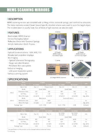
                                                                    A-Series                    B-Series
          | FEATURES
          · Electrostatic MEMS Scanner
          · Various Packaging Option
          · Reflective Mirror with Torsional Springs
          · Simple Fabrication Batch Process


          | APPLICATIONS
          · Optical Communications - VOA, WSS, TLS                 2D Single                   2D Single
                                                                 MEMS Scanner                MEMS Scanner
          · Miniaturized projection displays                     (Gimbaled Type)            (Gimbal-less Type)
         · Bio imaging
           - Optical Coherence Tomography                           C-Series                    S-Series
           - Finger vein identification
           - Handheld Skin care system
         · Industrial imaging
           - LCD panel inspection system
         · Various scanning system

                                                              1D Single MEMS Scanner       1D Array MEMS Scanner
          | SPECIFICATIONS
                           Series                 A-Series                       B-Series
                                                                                                        unit
                           Part No.      A1-C0505        A1-C0808       B1-C0808       B2-C1010**
                          Mirror Size     Dia. 1.0     Ellipse 2.3x3.0   Dia. 2.0        Dia. 2.5       mm
                            Mode                Quasi-Static                    Quasi-Static
                        Resonance Freq.     210            230             800            600            Hz
              Axis-1
                          Q-S Freq.        < 25            < 20           < 100           < 50           Hz
                        Mirror Tilt Angle  ±3 @120       ±2 @120        ±5 @120         ±3 @180       deg. @Vdc
                            Mode                 Resonance                    Same with Axis-1
              Axis-2    Resonance Freq.    1650            1800            --              --            Hz
                        Mirror Tilt Angle  ±3 @60        ±3 @60            --              --         deg. @Vdc
                  Package Type                  CLCC + PCB              CLCC + PCB        COB         (Default)

                           Series                 C-Series                      S-Series**
                                                                                                        unit
                           Part No.      C1-C1208       C2-uC3216       S1-AP025        S2-AP025
                                                                        Sq. 0.29x1      Sq. 0.29x1
                          Mirror Size     Dia. 4.0        Dia. 1.0                                      mm
                                                                         for Each        for Each
                            Mode                Quasi-Static                    Quasi-Static
                        Resonance Freq.     400            600            4,000           4,000          Hz
              Axis-1
                          Q-S Freq.         <50            <50             100            100            Hz
                        Mirror Tilt Angle  ±5 @120       ±5 @30         ±4 @100         ±2 @100       deg. @Vdc
                  Package Type             COB            TO-46           COB             COB         (Default)

          * The specification of the product can be changed without advanced notice.
          ** Developing
   6   7   8   9   10   11   12